6-Foot Dome Assembly
|
FEATURED 6 FOOT DOME – ASSEMBLY The photos below represent a sequential visual log of a 6′ dome construction process. |
|
| The 6′ diameter “PRO-DOME” (standalone) observatory provides all the convenience and protection of large observatories but in a limited space. Its small size allows installation just about anywhere and is less imposing in communities where neighbors have concerns about their view of your property. Though compact, the 6′ dome will easily accommodate a Schmidt-Cassegrain up to 12″ or, depending upon the mounting design, a 6″ Newtonian. There is space for you and a guest, but for larger groups, a 10 or 15-foot dome is more appropriate. The PD6 has a 74″ diameter, 45″ high wall sections, and a 30″ wide slot opening with a two-piece up-and-over shutter. The door is 19″ wide and opens all the way up into the shutter opening. Your dome must be bolted to a secure foundation. The base has a 3″ wide internal flange for easy mounting. Assembly time required is approximately 1 day for two people. | 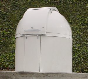 |
Assembly Steps
|
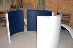
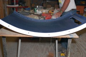
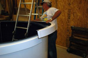
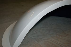
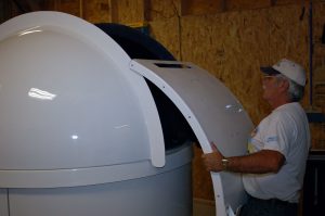
The main “structure” portion of the PD6 is made up of three wall sections and a door. When assembled, the result will be a 72″ circular building awaiting mounting of the dome. One of the keys to a properly working observatory is roundness – especially at the reverse flange on the top of the walls. Fiberglass has natural flex capabilities and “adjustments” can be made both at the point of bolting the sections together and mounting on the pad or deck.
|
|
|
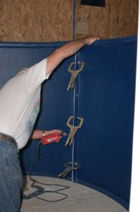
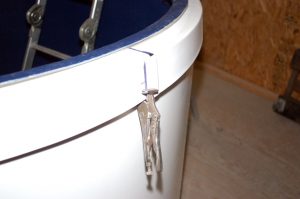
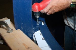
One of the easiest ways to work with the wall sections is the use of clamps to hold the section flanges together prior to drilling the bolt holes. The clamps can securely hold the dome position both when making measurements (roundness and circumference) and when drilling. The clamps also allow an easy way of making necessary adjustments during the process.
|
|
|
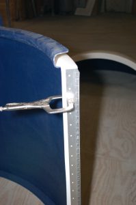
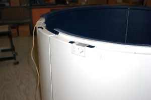
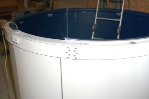
A flat straight metal strip can be used to keep the tops of the wall sections level as they are drilled and bolted together.
|
|
|
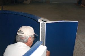
The door hinge is mounted onto the right wall section edge for the HD6T door. The hinge is 44″, which will allow about 1/2 inch at both the top and bottom.
|
|
|
After The hinge is mounted on the right wall section, the door is lined up, drilled, and attached to the open side of the hinge.
|
|
|
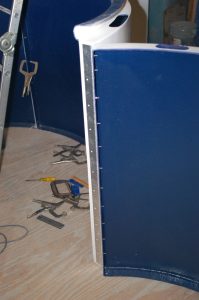
The door is now fully installed
|
|
|
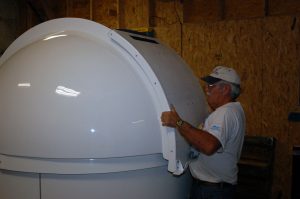
The left wall section can now be bolted into place.
|
|
|
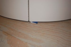
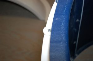
When the dome is installed on the pad or wooden deck, it will be necessary to shim up the dome on either side of the door by about 1/8 inch so that the door can swing open and close. The gap can be filled with a spray foam material (like “Great Stuff”) before caulking.
|
|
|
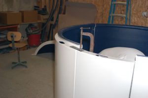
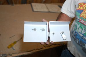
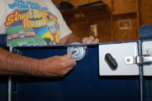
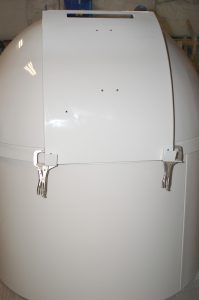
The door is secured with an upper latch mechanism and a lower drop-down deadbolt. Once assembled, the owner will open the shutter, reach in to unlatch the upper lock, turn the small black handle to raise the deadbolt (attached by a small cable), then swing open the door.
|
|
|
Placing the upper latch, drilling holes, and bolting into place.
|
|
|
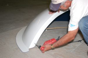
The next step is to prepare the front shutter. The photo to the right shows a completed front shutter.
|
|
|
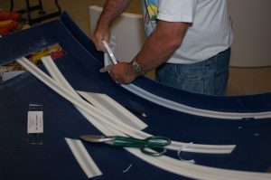
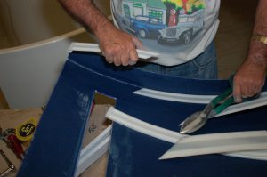
There are four glide strips, each with a “hooked” edge on one end. The hooked end is pressed onto one edge of the shutter and lays down on the shutter next to the side flange. One strip starts from each end and overlaps. The best approach is to make a diagonal mark in the overlap area, then cut both strips so that they will cleanly butt up against each other when the tape is pressed down.
|
|
|
Remove tape cover and press into place.
|
|
|
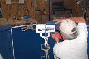
If ES6 electric shutter system is to be installed, this is the time to mount the ES front shutter parts. In the photo, the “T” pulleys are being installed. Note that small notches must be cut from the glide strips just installed for the “T” bracket to meet the proper measured location. (See the ES instructions and photo CD).
|
|
|
The last item installed on the front shutter is the shutter handles. They are mounted back-to-back (inside and outside, sharing bolts). See the instruction manual for placement measurements.
|
|
|
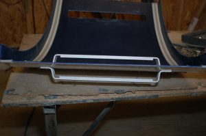
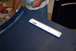
The Top shutter section will have the front and rear latch bars and the Shutter Wind Restraint “j-guides” installed.
|
|
|
When mounting the latch bars use the hole markings on the shutter as guides, but also make sure that they are parallel to the shutter edges and not mounted at a slant. Note that the “sharp” edge faces to the center on both latches.
|
|
|
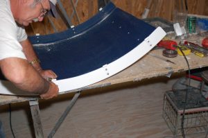
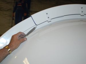
The “j-guides” are mounted 4″ from each end, with the other two evenly spaced between. They are positioned such that the loop end extends beyond the shutter flange edge.
|
|
|
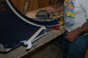
The rear shutter panel is prepared by drilling the holes that will mount the panel to the two dome halves. These holes will be used as guide holes for the dome flange when positioned and ready to bolt together. The shutter catches are positioned and mounted at the bottom of the rear panel (the end opposite the slot and beveled edge.
|
|
|
A plastic template is provided to locate the holes in the sidewall section for the roller wheels and on the top (under reverse flange) for the side roller disks. Small guide holes are drilled using the template, then re-drilled to the correct size once located.
|
|
|
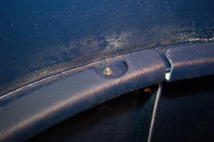
The side rollers are mounted on the upper surface between roller wheel openings. The self-tapping bolt is tightened, but still allowing free turning of the roller. The side roller extends out from the wall approximately 3/16″ and protects the Dome Support Ring from coming into contact with the wall when rotating.
|
|
|
The roller wheels have been made for us by a company in Germany for nearly 15 years, and have proven to be very durable and dependable. They have a sealed bearing system and hard rubber surface which is resistant to wear. The wheel is mounted up through the molded wheel openings and extends approximately 1/4″ above the top surface of the wall. A sleeve bearing, washer, and dust cup are used in the mounting assembly.
|
|
|
The Dome Support Ring (DSR) is made up of two large sections and a swing-out for the door. The sections have overlapping flanges to allow the proper adjustment to fit the circumference tolerances (see that table on page 18 of the manual.
|
|
|
When properly adjusted, there will be a gap of approximately 1/4 inch between the DSR and the wall completely around the circumference. One suggestion is to get 1/4 spacers (wood scraps for example) and tape 4 or 5 to the wall around the dome to assist in adjusting the DSR.
|
|
|
When the final positioning is accomplished the DSR sections are bolted together at the overlaps.
|
|
|
The dome halves are prepared by first drilling the holes where the dome will mount onto the DSR. Spacing is in the manual. This is on the “equatorial flange” not the slightly larger flange that runs the length of the shutter opening that the shutters ride upon.
|
|
|
Dome half with DSR mounting holes drilled.
|
|
|
Edge location measurements are mad and the DSR is marked accordingly. The dome half can be set up onto the DSR at the marks.
|
|
|
The dome half is adjusted to be as close to flush with the DSR skirt (outside) as possible (cosmetic).
|
|
|
Both dome halves are now resting on the DSR. They are not bolted into place at this point, just positioned at accept the rear shutter panel.
|
|
|
The bottom location of the rear shutter panel is measured then marked on the dome half shutter flange. The rear panel goes on with the latch bar slot at the top.
|
|
|
The rear panel is placed so that the side flanges slide over the dome half shutter flanges and are positioned up to the proper height based upon the bottom markings.
|
|
|
With clamps holding the rear shutter panel in place, a spacer (see manual, and two pictures down – a section of 2×4 works well) is placed to keep the front of the shutter opening at the proper spacing. Final adjustments are made (if needed) to re-position the dome halves on the DSR and make sure that visually the dome joints match. The holes are now drilled into the dome half shutter flange (using the holes in the rear panel as guides) and the rear panel is bolted into place.
|
|
|
The dome can now be bolted into place. The dome halves are attached to the DSR with 12 (six on each dome half), 3/4″ flat head machine screws from bottom up with nut and washer on top.
|
|
| The holes made earlier in the equatorial flange of the dome half are now used as guides for drilling matching holes in the DSR. The access hole in the reverse flange allows an open, easy-to-reach drilling point. |
|
|
The bottom side hole in the DSR must be countersunk to assure the flat head bolts are flush with the DSR underside.
|
|
|
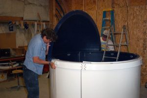
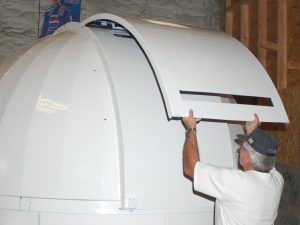
The final remaining steps in the construction are the placement of the shutter system and installation of the shutter Wind Restraint System. The front shutter is simply placed on top of the rear shutter panel, high enough that the handle is past the top of the rear panel. The handle will keep the front shutter from sliding back down. Note the “large” slot in the bottom portion of the top shutter. This slot will pick up the large latch bar on the top shutter and solidify the shutter system. |
|
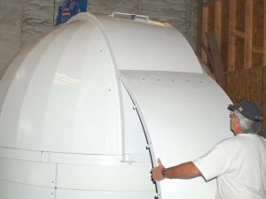
| Note: This and the next 3 photos are of a PD10, but the process (and images) exactly the same as on the PD6. | |
|
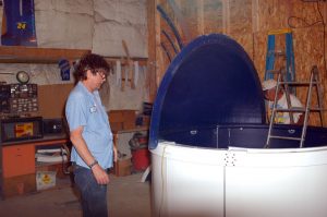
The top shutter is simply lifted up and placed into the rear shutter catchers laying against the rear shutter panel and overlapping the front shutter. The large latch bar is up while the shorter latch bar is on the lower side of the shutter piece.
|
|
|
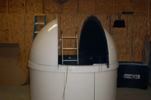
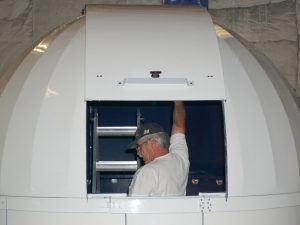
From the front of the dome, grab the handle and start sliding the front shutter forward. After a short distance, the large latch bar on the top shutter will drop into the slot and lock in place. The top shutter will now start moving forward (towards the close position) with the front shutter. Close the shutter all the way (until the rear latch bar falls into the slot in the rear shutter panel and locks into place. The shutter can now be opened and closed as desired.
|
|
|
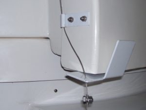
The last installation step is the Wind Restraint System on the outside of the dome. With the shutter, all the way closed, measure and mount the spring post and the small guideposts on each side of the dome. Note that the spring post measurement is down from the leading side of the TOP shutter and thus will be about 28 or so inches up from the bottom on the six-foot dome. The small guideposts are spaced towards the rear and are simply meant to keep the restraint cable from rubbing up and down the dome side as the shutter opens and closes.
|
|
|
The last step in the Wind Restraint installation is attaching the cable. The looped end of the cable attaches to the spring mechanism, feeds up through the j-guides mounted on the top shutter, and through the small hole in the rear shutter catchers. A split-bolt is used to “lock” the cable into place. With the shutter still closed, the slack should be pulled out of the cable and the split-bolt attached leaving about 1/4 inch space for slack. The picture to the right is with the shutter all the way open, which results in more slack in the cable. Your dome is now ready for many years of service! |
|


Hours
Monday through Friday:
7:00 am to 4:00 pm.