15-Foot Dome Assembly
|
FEATURED 15 FOOT DOME – ASSEMBLY The photos below represent a sequential visual log of a 15′ dome construction process. |
|
|
The HD15 is our 15-foot diameter observatory dome, designed for mounting on an existing structure. The base ring is a “solid” design with a splice plate access. The series of assembly photos provided below were taken during the preassembly of another HD15 of this exact design/configuration. These photos are not meant to replace the assembly manual and not every step is shown in full detail. They will provide a very good overview and hopefully be of value. |
 |
Assembly Steps
|
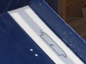
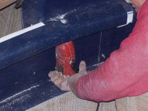
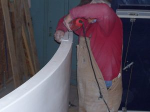
Several sections of the HD15 require initial preparation, including measuring and drilling “guide” holes. There is no right order to this prep work, and in this case, the Preassembly Tech started with the shutter sections. A new “Bolt Hole Drilling Guide” has been added to each assembly manual and is broken into “guide” and “final” bolt hole drilling steps. Most of the prep work can be done indoors using a workbench if desired. A good first step is to check the leading edges of the shutter sections and latch bar slots to make sure that it is not a “sharp” edge that can catch on other fiberglass edges. The edges are fled at the plant but may need a little additional touchup. |
|
|
|
|
|
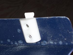
The prep work on the REAR shutter section is done in three steps. First, the rear Shutter Catchers are positioned, and the hole locations are marked and drilled. The rest of the prep work should be done before the Catchers are actually mounted to protect the cable “ear” which extends out from the shutter edge and makes handling the section more difficult.
|
|
|
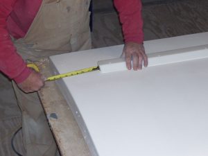
The REAR shutter section will be bolted into place bring them together with the right and left dome halves when the dome to mounted onto the DSR. The “guide” holes can be now drilled (and countersunk on the outside – white – surface). Later, when the section straddles and is properly positioned over the rear dome quadrant flanges, these holes will be used to drill the “final” mounting holes through the dome flanges.
|
|
|
The ES15 electric shutter motor assembly location is measured, and the motor assembly is placed on the shutter rear section in the proper orientation and location. The hole locations can then be marked, the motor assembly removed and the hole drilled. Because of the weight, the motor will not be mounted until the REAR section has been bolted into place onto the dome halves.
|
|
|
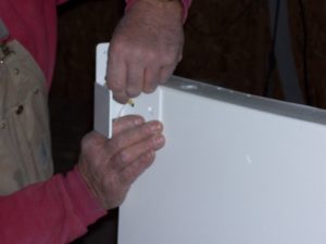
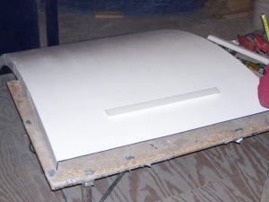
The prep work has now begun on the FRONT Shutter section. Locations are measured and marked for the handles, Deadbolt Lock assembly, and deadbolt lock receivers.
|
|
|
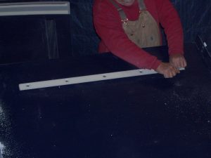
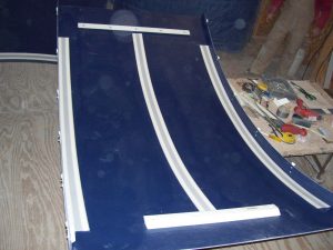
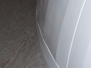
The FRONT Shutter section will have shutter glide strips running the entire length, butted against the shutter side flanges. There are five lengths of shutter glide strips. First, two full-lengths are hooked onto the front edge of the shutter and extended out towards the rear (stopping just short of the latch bar slot. Do not remove the protective paper at this point. Two things to keep in mind when applying the glides – the fiberglass surface must be cleaned with the included “Goof-Off” prior to adhering to the tape, and that this process should be done at 60 degrees or warmer (you may need to do this inside).
|
 |
|
Locate the Shutter Cable Clamp Assemblies (SCCA) into position and trace the unit onto the shutter glide strip (which will be “in the way” for final assembly). Using a razor knife, cut away the traced profile from the glide strip (on each side). Drill out the mounting bolt hole through the shutter fiberglass. The SCCA will need to mount flush to the FRONT shutter surface.
|
|
|
Making a diagonal cut remove approximately 18″ at the back end. With the shutter surface cleaned with the “Goof-Off” and the SCCA slot cut out, the paper tape protection can now be removed and the glide strip placed down into place. Use a smooth “tool” and run back and forth with moderate pressure to make sure that good adhesion is made. Use two of the remaining three glide strips to hook over the back edge of the FRONT Shutter section and lay forward – overlapping the pieces just mounted from the front. Mark overlap at the diagonal cut, remove the glide strip and cut off the short adjoining section. Push back onto the shutter edge then remove the paper protection to press into place, butting together at the diagonal cuts. Save the long “left-over” as it will be used on the TOP Shutter section. |
 |
|
The SCCA hardware is now bolted into place.
|
|
|
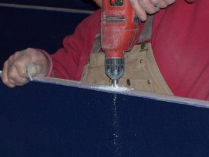
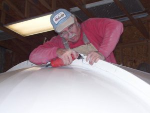
The Tech is now working with the TOP shutter section first in this sequence. The locations of the j-guide holes have been measured out and he is now drilling those. The bolts holding the j-guides are flat-head and the holes must be counter-sunk on the inside (blue) surface.
|
 |
|
After measuring the j-guide locations, it is easiest to just use the guides themselves as a template for drilling the holes. They are positioned so that the looped end hangs over the shutter flange edge.
|
|
|
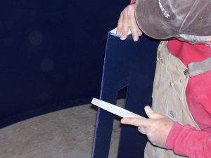
The holes need to be drilled for the long and short latch bars prior to mounting onto the TOP Shutter section. Even though they will be mounted on the inside (blue) surface, the easiest approach is to place them in the proper location on the outside (white) surface and use them as a drilling template for the holes. The measurement/placement are critical for these items and special attention is given to assuring that when mounted they will be parallel to the edge of the shutter section.
|
|
|
Again, the measurement/placement is critical for these items, and special attention is given to assuring that when mounted they will be parallel to the edge of the shutter section.
|
|
|
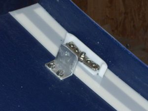
A shutter spacer block is attached at the rear of the TOP Shutter section, sharing the holes/location of the rear-most j-guide. These spacer blocks help keep the TOP Shutter section centered as it moves back and forth in normal operation.
|
|
|
The remaining j-guides are now bolted into place.
|
|
|
The TOP Shutter section is flipped over and the two latch bars are attached. The “knife” edge will be facing the center of the shutter section for both.
|
|
|
Make sure the remaining glide strips have adhered to the inside surface of the TOP Shutter section. Make sure that the surface is cleaned first with the “Goof-Off” and the strips are applied at room temperature or warmer. The last complete strip is laid down at the center and each hooked end cut off far enough down to allow a fit between the two latch bars. The remaining hooked end is cut off each of the two long “scrap” pieces left from the FRONT Shutter section then mounted, centered, and against the shutter side flanges.
|
|
|
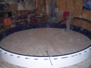
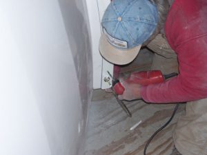
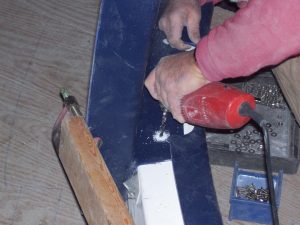
With the shutters finished, work moves on to the base ring. The manual actually starts with the base ring but the order is not important. Locate the wheel cutouts and use the template to drill the wheel mounting holes. The four longer holes (leftmost in the picture to the right) are for the ED rotation motor assemblies and should not be drilled at this point. Mount the main rotation wheels at this point.
|
|
|
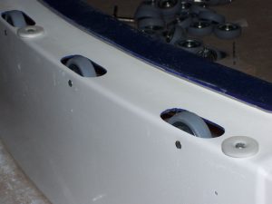
The side roller (small white disks) locations are identified and using the plastic template provided, drill the mounting holes on the base ring top surface. The side rollers are mounted with a “lock nut” which allows the bolt to be tightened in place while still allowing the side rollers to freely spin around.
|
|
|
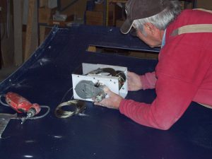
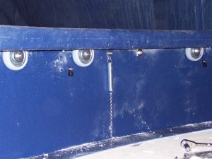
This is an inside photo of the main rotation wheels mounted in place.
|
|
|
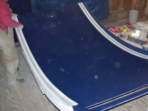
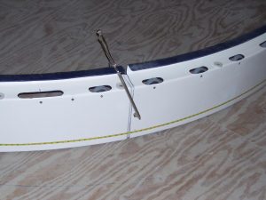
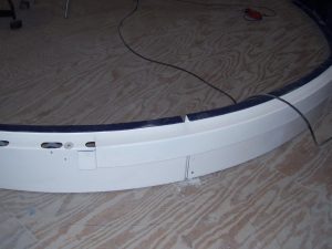
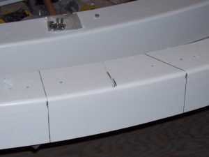
The base ring sections (all are the same) are formed together to make a complete ring. Notice that there are overlapping “male” and “female” ends on each section. Push the sections completely together and then take a circumference measurement. Using the table in the manual adjust each joint to bring the circumference within the tolerances. Try to spread and adjust overall joints to have a uniform appearance.
|
|
|
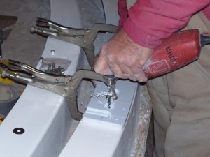
Use clamps to hold each section joint in place as you make adjustments.
|
|
|
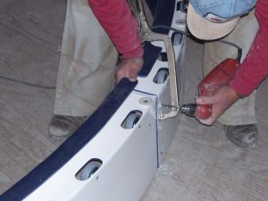
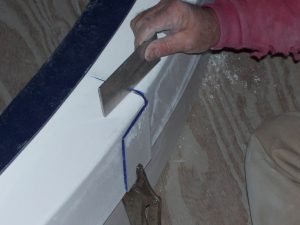
Once the desired circumference is obtained, holes can be drilled in the overlap and the sections bolted together. Guide holes were first measured and drilled in the outer (“female”) section end. These make the final drilling more accurate and easier to complete.
|
|
|
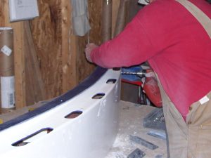
Once the base ring is of proper circumference, the DSR sections are placed on the base ring with the connection flanges over-lapping. Use duct tape to hold the sections together while taking the circumference of the DSR. Adjust the overlaps in or out (pull up tape then press back) to get circumference to fall within tolerances (table in manual). Once the DSR is properly set drill and install screws.
|
|
|
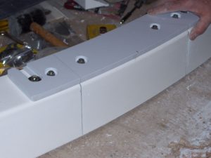
The HD15 does not have a door section and utilizes a “Splice Plate” to provide access for possible future repair needs. This is an optional install piece but highly recommended. The Splice Plate is placed on the front of the DSR (evenly centered on one of the DSR sections) and used as a hole drill guide to drill the bolt holes in the DSR. Clamps will hold it in place and prevent movement while drilling.
|
|
|
Once the holes are drilled, use the pencil markings on the Splice Plate to “transfer” corresponding markings onto the DSR. These will be the guides for cutting the DSR. A standard “hack saw” can be used to make the cuts through the DSR. You will end up with a removable section of DSR that will be held into place by the Splice Plate. NOTE: The DSR and NOT the Splice Plate is cut |
|
|
Use the provided hardware to bolt the Splice Plate into place.
|
 |
|
Through the many steps of preparing the DSR, stop from time to time to make sure that the joint seams stay relatively level with each other. Small adjustments can be made before the final attachment holes are drilled.
|
|
|
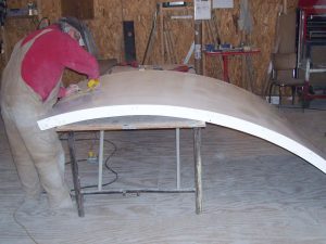
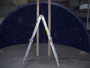
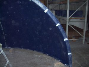
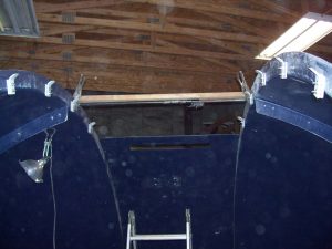
The dome portion of the HD15 comes in four quadrants, which will be formed into two dome halves prior to attaching to the DSR. Review the manual and Bolt Hole Drilling Guide for measurement and drilling of guide and final holes. The dome quadrants are very large, heavy, and unstable before being bolted into dome halves. To prevent accidents, we highly recommend using a bracing system to stabilize the quadrants while you are working on them.
|
|
|
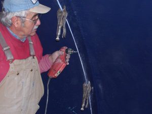
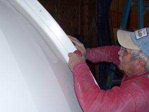
The dome quadrants are attached (make sure that you have one “front” and one “rear”) through the “Greenwich” flanges. One side is measured and “pre-drilled” prior to setting them up and bringing the two together. Use clamps to align and hold the corresponding Greenwich flanges. Check the outside (white) joint to see that they are flush and even. Once properly in place, the guide holes can be used to drill the final holes in the other flange and the dome halves bolted together.
|
|
|
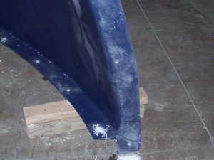
The “guide” holes for mounting the dome half tote DSR are now measured and drilled in the dome Equatorial Flange.
|
|
|
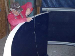
The mounting of the shutter cable pulleys is easier when the dome half is sitting on the floor in an easy-access position.
|
|
|
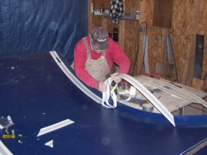
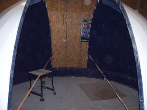
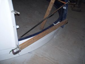
The dome halves are set up on the DSR (mark the front locations for placement. They are not actually bolted onto the DSR until the REAR Shutter panel and front spacers are in place to properly control the shutter opening dimensions. Fiberglass has a great deal of flex and will tend to want to stretch “outward” from the DSR at each end. The easiest way to deal with this flex is to use straps or ropes to force these into the proper shape. Adjustable cargo straps (see photo) work very well.
|
|
|
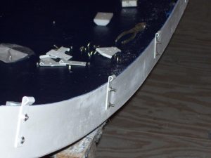
The REAR Shutter section is placed over the rear flanges of the two dome halves and positioned
|
|
|
Clamps will hold the REAR Shutter section in place while drilling final mounting holes
|
|
|
Using the “Guide” holes drilled earlier in the REAR Shutter section, drill the bottom final holes through the rear flanges of the two dome halves (both sides. Install and tighten the flat head bolts, washers, and nuts to set the proper width at the rear.
|
|
|
Install a spacer (carefully measured 2×4 works well) at the very front lower edge of shutter opening to “force” the proper.
|
|
|
Install a second spacer at the top of the shutter opening just past the zenith. This will also force the dome halves and the upper portion of the REAR Shutter section to become flush and in line.
|
|
|
Make sure that the REAR Shutter section is pushed down onto the rear dome flanges as far as it will go, and then proceed to drill the remaining “final” holes in the dome flanges by using the existing “guide” holes in the shutter section.
|
|
|
Take care to make sure that the last (top) bolts hole is drilled with the top edge of the REAR Shutter section flush with the dome flange. You will need to push down on the shutter edge while drilling the final hole. Make sure all bolts are in and tightened.
|
|
|
Before drilling and bolting the dome down to the DSR, go around the outside and check for “fit” between the outside dome surface and the DSR surface. This is mostly “cosmetic” as the shutter spacing has been set, but it will make the overall dome uniform and consistent in appearance. A rubber mallet or the palm of your hand can be used on the dome surface (inside or out) to nudge the dome in line with the DSR.
|
|
|
The dome can now be bolted down to the DSR. You will want to work with one side at a time and do the first and last bolts before the middle ones. Slowly rotate the dome so that the front-most Guide hole (pre-drilled in the dome equatorial flange) lines up with the access hole in the base ring. Using the guide hole, drill the final hole down through the DSR.
|
|
|
Since Flat-Head bolts are used from the bottom of the DSR up (washer and nut on the top of the dome equatorial flange) the holes need to be countersunk from the bottom (using a lower access hole). Insert and tighten the bolt, rotate the dome so that the last rear-most Guide hole is in the access hole, and repeat the process. The rest of the holes can now be drilled and the dome half completely bolted into place. The entire process is repeated for the other dome half. Once the dome is completely secured to the DSR, the front spacers can both be removed.
|
 |
|
The four electric dome drive motor assemblies (ED) should now be installed and wired. The assembly manual contains a separate section on ED installation.
|
|
|
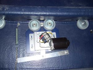
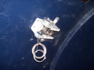
The electric shutter drive motor assembly (ES) should now be installed and wired. The assembly manual contains a separate section on ES installation.
|
|
|
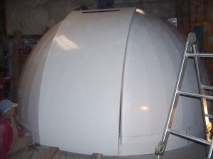
A second view showing the location of the ES motor assembly. At this point the FRONT shutter should be placed on top of the REAR Shutter section, high enough up that the deadbolt lock assembly and the SCCA units are passed the upper lip of the REAR section. The TOP Shutter section is then simply placed over the FRONT shutter section and resting in the Shutter Catchers. Make sure that the TOP Shutter section is oriented properly.
|
|
|
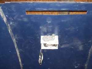
The sliding contact assemblies allow the power to transfer up to the ES motor assembly and define the “Home” position of the dome. The contact plates are mounted on the reverse flange of the base ring while the adjustable brackets holding the contact loops are mounted onto the dome wall.
|
|
|
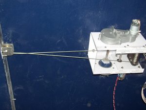
The ES15 shutter cables are attached while the shutter is fully open. Both the short and long ends terminate at the SCCA where they are clamped into place. A complete description of the paths the cables are routed through can be found in the manual.
|
|
|
Another view of the cables coming out one side of the ES15 motor assembly. Remember to leave the cable tension clamps in place as the cable is being strung – then removed before the motor is operated for the first time. Cables will need more tension after the split-bolt tension clamps are removed. Save these clamps as you will need to reattach in the future if releasing the cables. Without tension, the cable will unwrap from the windlass shafts inside the motor assembly.
|
|
|
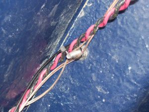
Several cables (red/black power, limit switches, etc.) run throughout the completed observatory. Small plastic cable clamps are provided but you can also use exposed bolts, ties, etc to secure the wires/cables out of the way.
|
|
|
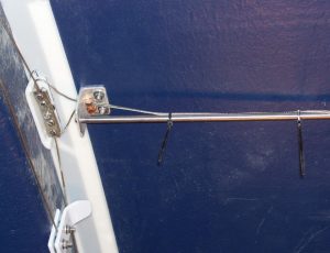
The ends of the ES shutter cables must be a foot or so in length after final adjustments. This will provide the ability to “grab onto” when making future adjustments. The cable ends must be secured out of the way of the shutter pulleys so a small hole exists in the deadbolt receiver bracket to feed them through. Also, this becomes a good place to “store” the cable tension clamps.
|
|
|
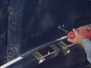
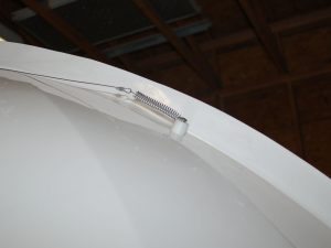
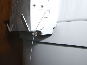
One of the final assembly steps is the installation of the wind restraint system. The wind restraint cable starts with the spring post mount onto the upper front portion of the dome, running through the TOP Shutter j-guides and terminating through the small hole in the Shutter Catcher “ears”.
|
|
|
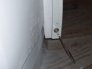
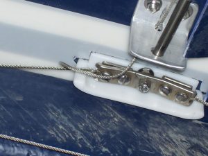
A split bolt is used to terminate and hold the cable in place. There should NOT be tension on the wind restraint cable. When the shutter is fully closed, there should be about 1/4 inch slack, which will be almost completely taken up when the shutter is all the way open.
|
|
Hours
Monday through Friday:
7:00 am to 4:00 pm.