10-Foot Dome Assembly
|
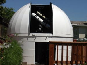
FEATURED 10 FOOT DOME – ASSEMBLY The photos below represent a sequential visual log of a 10′ dome construction process. |
|
|
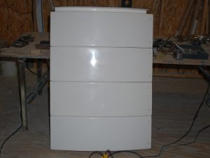
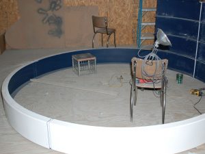
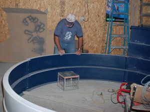
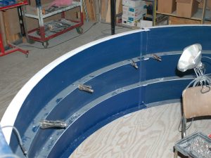
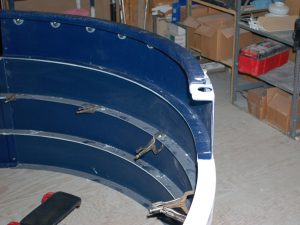
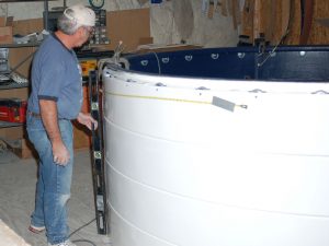
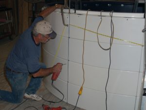
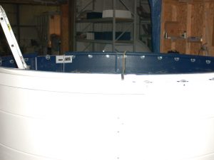
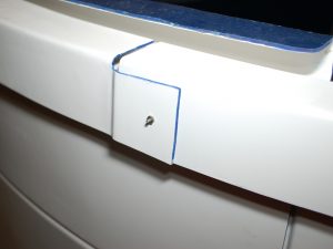
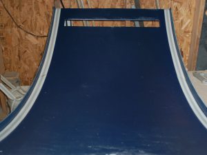
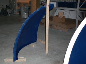
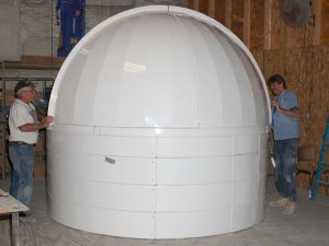
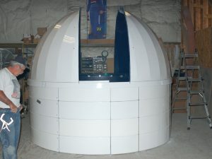
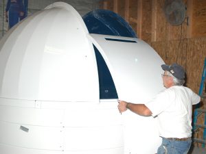
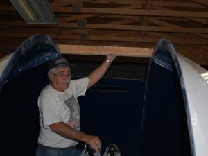
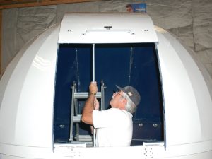
The dome in the photo to the right is a PD10 with three wall rings – including a “split door” dividing the base ring (which MUST stay connected away from “home” – or while the dome is moving) door segment and the three wall ring door segments. This allows for the ability to open the entire door when at “home” (to enter the dome unimpeded), and to open the lower three-door section (36″) in order to leave the dome while in operation and not “home”. The series of assembly photos provided below were taken during the preassembly of another PD10 of this exact design/configuration. These photos are not meant to replace the assembly manual and not every step is shown in full detail. They will provide a very good overview and hopefully be of value. |
 |
Assembly Steps
|
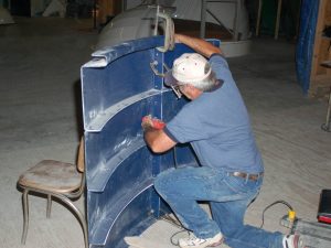
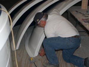
The PD10 wall and base rings are made up of segments that must be bolted together to form the ring. These segments are; three full ring sections, two stub sections (on either side of the door), and one door section. The manual describes building one, ring and then simply states that you should follow the same method for each of the additional wall rings. This is one approach, but if your observatory has multiple wall rings, many people (including our preassembly Tech) find it easier to build the stacks of stubs and door sections first, the build additional rings one at a time.
|
|
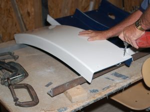
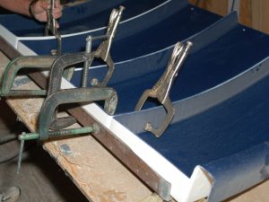
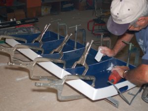
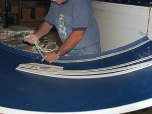
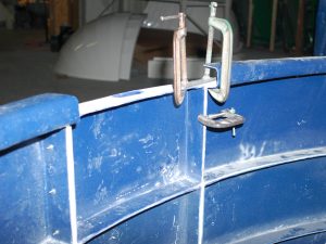
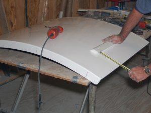
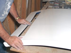
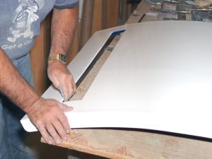
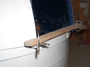
| As you will see throughout this photo sequence, clamps become a very important part of the tool kit needed to assemble the dome. Vise grip types are normally the easiest to work with, but just about any style will do. You should start the project with at least 4. In these photos, you will note the use of more than that, but it is just a function of the approach. For example, this first series of photos show all four stub sections assembled at the same time when it would be just as easy to do two at a time. Note the use of “straight-edge” objects (like lengths of steel or aluminum scrap) to keep edges flush and inline.
|
|
|
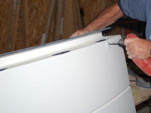
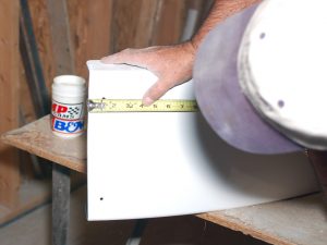
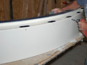
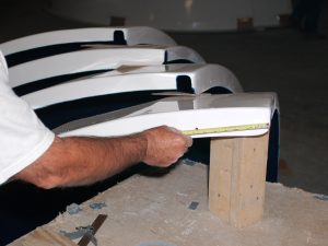
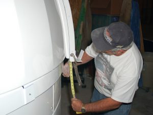
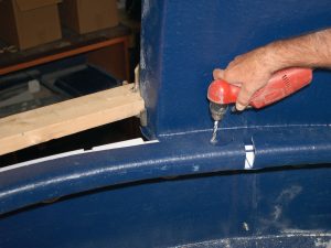
Measurements assure the proper location of holes needing to be drilled.
|
|
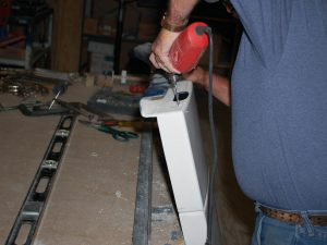
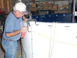
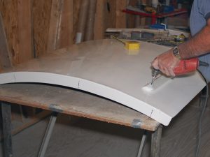
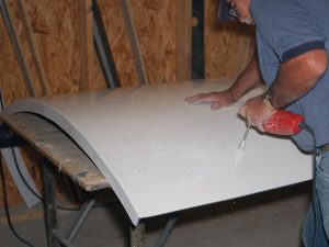
| Drilling through fiberglass is quite easy and only “wood” bits are required. A small cordless drill will make the process easier and faster.
|
|
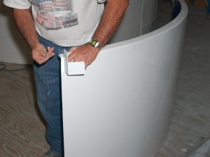
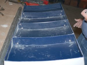
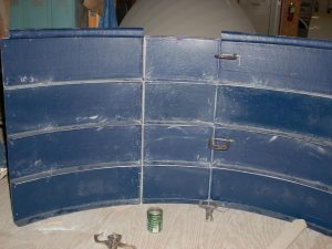
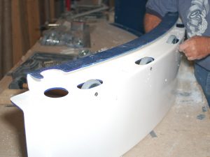
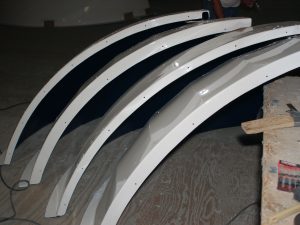
| The first “stack” of wall stubs is completed. The same process will be repeated for the other stub sections ad well as the door sections.
|
|
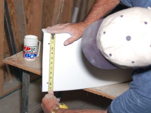
| The holes for the rotation wheels and the side rollers are drilled in the base ring portion (top) of the stub stack. A template is provided for locating the exact measurement.
|
|
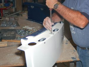
| The template allows small “guide holes” to mark the exact hole location. The same template is used for both the side roller and wheel holes, so make sure it is turned in the right direction before drilling guide holes.
This photo shows the wheel holes being drilled out using the guide hole.
|
|
|
The wheel and side roller holes are finished in this “stub” section.
|
 |
| The segments making up the door are bolted together with two carriage bolts between each.
|
|
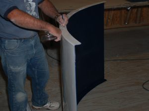
| The door has been completed. Aligned, drilled, and bolted together.
|
|
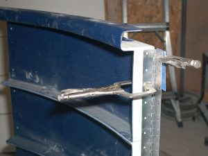
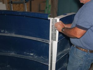
| The door hinge is now installed on the right side stub stack. Remember that the designation of right and left is always from a reference point of standing outside the dome looking in.
|
|
| The hinge is attached by using every other bolt hole starting with the first hinge and ending with the last hole (even if the second to last happens to have a bolt. Securing the hinge in place the holes can be drilled into the right stub flange. The hinge is one inch shorter than the height of the door/stub stacks, so it should be positioned about 1/2 inch from the top.
|
|
| Once the holes are drilled on the stub side, the door is positioned against the stub and secured in place. Again, a flat metal piece can help assure that the top surfaces of the door and stub are even.
|
|
| Once the door is secured in place, the bolt holes for the door section can be drilled.
|
|
| Using the holes drilled in the stub section as guides, holes are drilled through the flange on the door side.
|
|
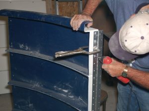
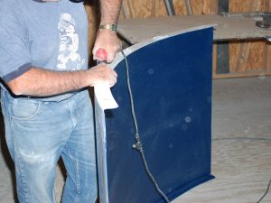
| The hinge can now be bolted to both the right stub section and the door. Note that in this assembly a “split” door will be made to allow the base ring to remain secure while the lower portion of the dome can swing-out. To facilitate this, the hinge had to be cut on the door side between the base ring section and the top wall ring section. A hand “hack saw” works well.
|
|
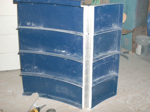
| The door is now properly attached to the right stub section.
|
|
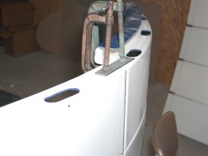
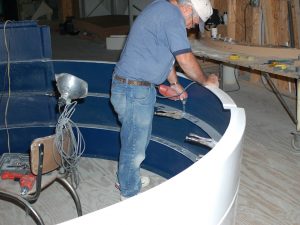
| The left side stub is lined up in place to get ready for the rest of the wall construction.
|
|
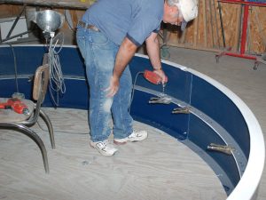
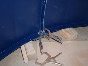
| Clamps are a great help in keeping parts/sections lined up and secured in place
|
|
| The left stub is now clamped into place to the door edge. (“Left” refers to standing on the other side (“outside looking in”)
|
|
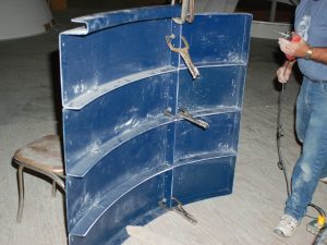
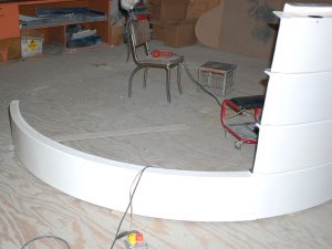
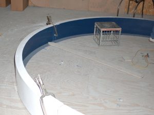
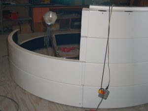
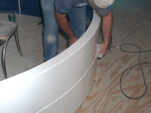
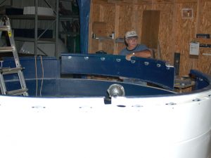
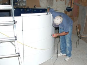
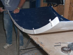
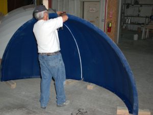
| The bottom wall ring can now be moved into place. The ring is made up of three identical sections with overlapping edges.
|
|
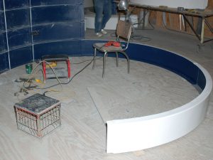
| The second section has been push into place.
|
|
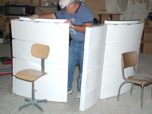
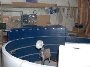
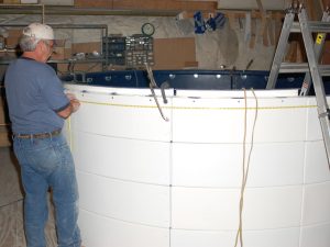
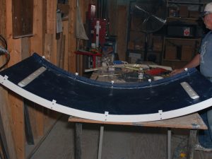
| Once the bottom ring is in place (three wall sections, left stub, door, right stub), it is important to make sure that it is both round and that the circumference falls within the tolerances (see table in the instruction manual).
|
|
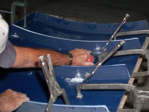
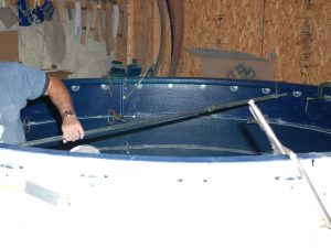
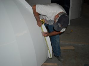
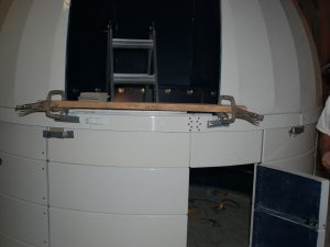
| An easy approach to roundness is to identify the center of the dome and measure a radius out. At our preassembly construction area, a board was cut to the correct radius length and is attached to a center bolt so that it can simply swivel a full 360 degrees.
|
|
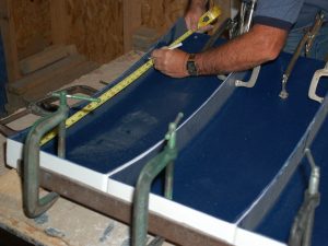
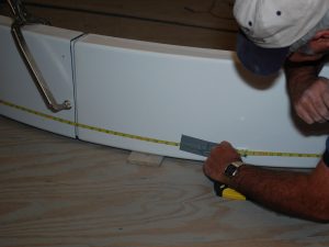
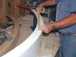
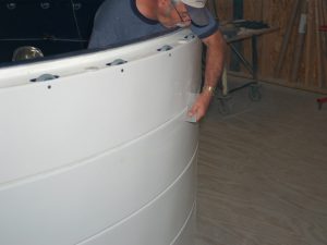
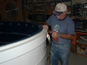
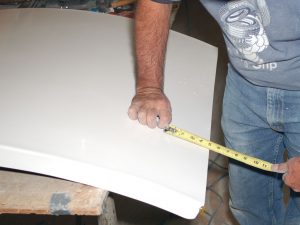
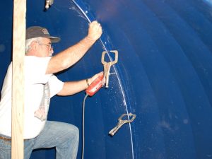
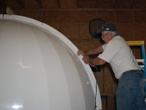
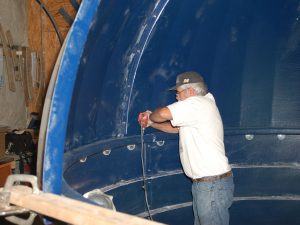
| A flexible tape measure is necessary to verify the circumference. The ring circumference can be adjusted by moving the section overlap joints. One of the thousand valuable uses of duct tape is to secure one end of the tape measure while bringing it around to the other side.
Two bolts are used to bolt the wall sections together at the overlaps. Once the bottom ring is set, the bottom bolt of the two will be drilled and bolted to hold the shape of the bottom ring as the other wall rings are constructed. All other overlap bolts (up through all rings) are saved for the end of the overall wall building process. This allows final adjustments at the end of wall construction before bolting all the seams.
|
|
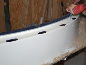
| Once the bottom ring is the proper circumference and is round, the wall sections for the next ring are prepared. The holes for attaching the sections together are measured and drilled like the dome on the first. The holes are only in the “upper” overlap and will be used as guide holes for the corresponding “under” section of the adjacent section once final bolting is started.
|
|
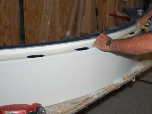
| Make sure that the wall section attachment holes are the proper distance from the edge.
|
|
| Same for top and bottom.
|
|
| The holes in the bottom flange of the second ring sections (for attaching the second ring to the bottom ring) are measured and drilled. This will be used as guide holes to drill down and through the top flange of the bottom wall ring AFTER the second ring has been put in place, then checked for roundness, circumference, and placement. This process will be followed exactly for the third and base (top) rings. |
|
| The second wall ring is laid out exactly as the first (bottom) was.
|
|
| The wall ring sections are “adjusted” at the point of overlap.
|
|
| A wooden block works to tap the ring in and get as flush as possible with the bottom ring.
|
|
| Once ring number two is in place (roundness verified as well as circumference). The holes for mounting the two rings together are drilled. The holes made in the bottom flange of the second ring during the prep stage are used as guide holes to drill through the top flange of the bottom ring. The two rings are now bolted together.
|
|
| The third ring goes up in the same manner.
|
|
| As before, the third ring is adjusted for roundness, circumference, and flush lineup with the second ring.
|
|
| Holes drilled through the “guide” holes made during ring prep and down through the upper flange of the second wall ring. Rings are then bolted together.
|
|
| The dome “Base Ring” will become the top “wall” ring. The prep for this ring is more extensive. Not only are the holes drilled in the bottom flange for ring attachment, but also the holes for side rollers and rotation wheels.
Measurements are made for the location of the side rollers.
|
|
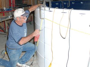
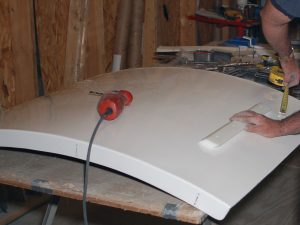
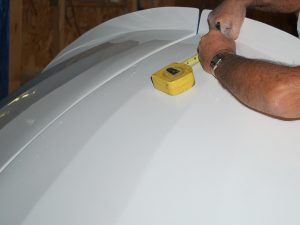
| Using the provided template, first, a small guide hole is drilled for the side roller, then the proper size is drilled out.
|
|
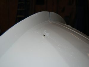
| Using the centerline of the wheel cutout and the wheel template, the holes for the rotation wheel bolt are made. Note, these holes are also counter-sunk so that the “flat head” bolt will be flush with the ring surface. Counter-sinking of holes is called for in other locations on the dome.
|
|
| The wheels are mounted in each of the hole cutouts in the base ring sections.
|
|
| The side rollers are mounted at the measured locations (between wheels – but not every wheel “pair”). Make sure that the self-tapping bolts are properly tightened, but that the side rollers still urn freely.
|
|
| The base ring sections are placed upon the wall stack, same as in the earlier wall ring steps.
|
|
| The base ring reverse flange is displayed in this photo.
|
|
| The last base ring section is worked into place by positioning the overlaps and pushing them together.
|
|
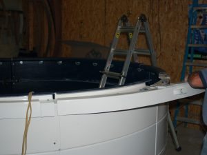
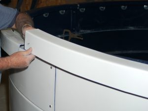
| As the base ring is clamped to the third (and topmost) wall ring you will want to check that rings are still flush and with seams lined up (for cosmetic appearance).
|
|
| A final circumference measurement is taken to assure that it falls within the tolerances on the table in the manual. This is the critical point since the DSR (Dome Support Ring) will be riding on the wheels at this point.
|
|
| It is a good idea to use a level to check the walls and assure that the rings have maintained vertical orientation. Since each wall ring was checked as it was drilled and bolted down, this should not be an issue.
|
|
| A final check for the roundness is now made at the reverse flange level. Again, this is the critical point for roundness as the DSR/Dome will rotate at this point. The overlap seams were not bolted together as each wall ring layer was assembled specifically to allow adjustments if necessary.
|
|
| Using the outside holes drilled during the prep work on the sections as guides, drill through the inside flange from the adjoining wall ring section.
|
|
| Bolt the top hole (remember that the very bottom of the bottom wall ring was bolted during that level assembly and continue drilling the attachment holes down the seam.
|
|
| The two bolts (at the very top and very bottom) will hold the seam in place as the rest of the holes are drilled then bolted (even though the seam is still clamped together).
|
|
| After the first seam is completed go across the dome to the opposite seam and complete the attachment there. The last two seams can be completed in any order.
|
|
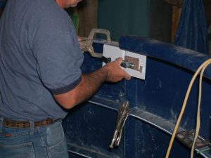
| The inside latch assembly is mounted with the handle section on the door segment and the receiver section on the left stub top ring segment.
|
|
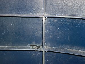
| When a split door design wall is constructed, a small bolt latch is mounted on the second level of the door sections. This will secure the “bottom” portion of the door while the inside latch secures the top. The draw has mounted on the outside also pulls together and secures the base ring portion of the wall.
|
|
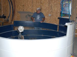
| The walls are now complete and ready for the assembly and mounting of the dome.
|
|
| The actual dome is mounted to a Dome Support Ring (DSR) which rotates by riding on the wheels. Once secured, the DSR (positioned inside the reverse flange portion of the base ring is “smaller” than the base ring/wall and thus is at NO risk of coming off the wall as long as it is closed and secure.
The DSR ring is made up of three overlapping segments (similar to the wall ring sections) with a door “swing-out” attached to one. The circumference of the DSR is critical (with respect to the base ring circumference) to allow free movement in the rotation of the dome. The differences equate to a gap of approximately 1/4 inch all the way around the base ring. In fact, it is suggested that 1/4 spacers be taped to the base ring for the initial positioning.
|
|
| The overlap sections should be taped together with duct tape to allow small adjustments as the circumference tolerances are met. Also, distribute the “gaps” evenly at the three junctions (do not have two butted tightly together and a “large” gap at the third.
Once the DSR is positioned properly and the correct dimension, the holes can be drilled at each overlap and the bolt inserted.
|
|
| The last seam will need to be lifted up to get the bolt in place.
|
|
| The DSR is not complete and ready for the dome.
|
|
| At this point in the construction, it is time to do the prep work on both the shutter sections and the dome quadrants in order to complete the final assembly steps. In this assembly, the top shutter is worked on first. The top shutter is the section with NO slots cut into it. The location of the wind restraint j-guides is measured and marked.
|
|
| The holes for the wind restraint j-guides are drilled out (five on each side for a total of ten on the 10-foot dome).
|
|
| The locations of the front and rear shutter latch bars are measured and determined.
|
|
| Make sure that both ends are exactly the same distance from the shutter edge to assure each latch is parallel with the shutter edges.
|
|
| Once the latches are positioned, the mounting holes are drilled. Note that the latches will be mounted on the inside of the shutter – it is just easier working on the outside to locate and drill the holes.
|
|
| The j-guides are bolted into place on both sides.
|
|
| The front and rear latch bars are bolted in place. Make sure that the nuts are tightened enough to pull the carriage bolt heads down flush with the outside surface. Also, note that the latch bars are both positioned so that the “point edges” are facing the center of the shutter section.
|
|
| The “top” shutter has not been prepared for final installation.
|
|
| Next, the “front” shutter is prepared. Both the “rear” shutter panel and the “front” shutter have latch bar slots cut into them. The “rear” panel is the narrowest of the three and the “front” shutter has a wider slot cut-out.
|
|
| It is a good idea to smooth the slot edges with sandpaper to make sure that there are no “sharp” fiberglass edges and to put a slight bevel to the top and bottom edges.
|
|
| The hole locations for the front handles are measured and marked.
|
|
| The handle holes are now drilled out.
|
|
|
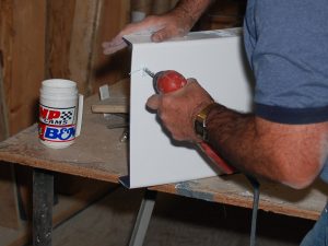
The front shutter will ride back and forth on the dome shutter edge flange and thus “glide strips” are provided to make this movement smoother. First, make sure that the shutter surface next to the edge flanges is cleaned with the “goof-off” provide to assure good adhesion. The glide strips come in four pieces, with a hooked end on one end. This hooked end will push onto the shutter edge and the strip will then lay down the inside surface. Strips will start from both ends and overlap in the middle. Do not remove the tape cover strips at this point. Make a diagonal cut through both strips somewhere within the overlap area to assure that they will butt tightly at that point. Start at one end by peeling away the tape cover and press the strip into place as you work towards the center.
|
 |
| The glide strips are shown in place and mounted. They should be right up against the side flanges of the front shutter inside on both sides.
|
|
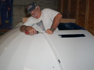
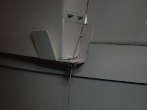
| The “rear” shutter prep involves measuring, drilling, and countersinking the holes up the side flanges, (which will be used to mount the rear panel to the dome halves), and mounting the shutter catchers on the outside bottom (shown in photo)The top of the rear panel is where the slot cut-out is located.
|
 |
| The dome itself comes in four quadrants. The left front and right rear are identical as are the left rear and right front. The quadrants all have one flange that turns outward (the shutter edge flange) and two flanges that turn inward (one to mount the two quadrants together to form a dome “half” and one that mounts to the DSR. The initial prep work on the dome quadrants is the drilling of the holes in the DSR mounting flange.
|
|
| There are five bolt holes in each quadrant. The two “end” holes are measured from the flange edges with the other 3 evenly spaced between.
|
|
| The four quadrants are now ready for assembly and mounting onto the DSR.
|
|
| Bolting the quadrants into dome halves is easiest done with two people. Otherwise, a 2×4 and clamp can hold the position as the work is done. Identify the left and right quadrants and bring them together at the “Greenwich Flange”.
|
|
| Make sure that the outside seam is even and that the DSR mounting flanges are flat and in line with each other. Clamp the two quadrants together.
|
|
| The bottom (DSR flange) is clamped, here using a flat metal piece to assure that the DSR flanges are level and in line. Note the holes in the flange which were drilled in the step above.
|
|
| With the seams in place and clamped together, the mounting holes are drilled and quadrants bolted together.
|
|
| While still on the ground, the hole locations for the wind restraint guideposts are measured and drilled. |
|
| The wind restraint cable will run from the shutter catcher on each side, up through the j-guides mounted on the top shutter, and to a spring guide post located partway up the front quadrant (which will be located later after the shutters are mounted. The guideposts simply keep the cable from riding up and down the dome side and making wear marks. They will be evenly spaced (from the first one located above the shutter catcher and approximately 2 inches out from the shutter side flange.
|
|
| The posts can be mounted while the dome is still down off the wall.
|
|
| After marking a front edge locator on the DSR (both sides), the dome halves are now lifted up and placed on the DSR. This is obviously a two-man job. It is just resting on the DSR and can be adjusted to the front edge mark and to be flush on the outside with the DSR ring. Since this step will be being performed outside, the first test to see what direction the breeze is come from (and plan another day if very windy). The dome halves make an excellent sail and become very hard to work within the wind!
|
|
| Both dome halves are in place and ready for the rear shutter panel cover installation.
|
|
| The rear shutter panel will slide up and over the outside of the shutter opening flanges (slot cutout up). Mounting holes were drilled (and countersunk since flat head bolts will be used) in the prep step.
|
|
| The proper position of the rear shutter panel is determined by a measurement down from the bottom edge of the dome shutter opening flange.
|
|
| Before bolting the rear shutter panel to the dome halves, and the dome halves to the DSR, it is important to assure that the shutter opening will maintain the correct width through the process. This can be accomplished by using two spacers (2x4s from the crate work very well. The first should be located at the very front of the shutter opening. The spacers can be made in one of two ways. The first is to cut to the exact width, place it between the shutter edge flanges of the two dome halves, and secured it in place with a small wood screw from the outside through the flanges. The second method is to measure the opening width on a longer 2×4 and then cut two 3/16″ slots partway through the board. The spacer can then push down over the slot edges. The front one will need securing with clamps.
|
|
| The second spacer will be located as close to the zenith as possible.
|
|
| The rear shutter panel is pushed down tightly against the dome shutter opening flange and using the holes in the panel as guides, drill the corresponding holes through the shutter opening flange.
|
|
| The panel is now securely bolted to the dome halves with flat head bolts. Make sure that the bolt heads are flush with the panel edge. If not, the countersink is not deep enough and needs drilling out slightly more.
|
|
| The spacers will remain in place while the dome halves are mounted onto the DSR.
|
|
| Using the access hole in the reverse flange, the holes can be drilled through the DSR (using the existing holes drill in the equatorial flange during the prep work on the dome quadrants as guides). Make sure that the dome is still positioned properly (front edge marks and flush with DSR on the outside). Start with the first bole and work back.
|
|
| The dome will carefully be rotated to bring each bolt position around to the reverse flange access hole. The holes through the DSR must be countersunk and secured with flat head screws coming from the bottom up. There is a lower access space for this. Once the dome is securely bolted onto the DSR, the two spacers are removed to allow the installation of the front and top shutters.
|
|
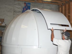
| The front shutter is carefully placed up on top of the rear shutter panel so that the front shutter handle is beyond the top edge of the rear panel and the shutter rests flat on the rear panel. The handle will “catch” on the top edge of the rear panel and keep it from sliding back down.
|
|
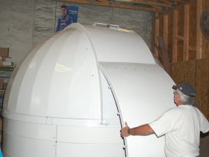
| The top shutter is now simply placed on top of the front shutter with the bottom resting in the two shutter catchers.
|
|
| The front shutter is pulled slowly forward. After a few inches, it will engage the front latch bar on the top shutter and then begin pulling the top shutter along with it. Close the shutter all the way and verify that the latch bars drop cleanly into both slots and securely “lock” into place.
|
|
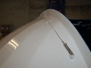
| The wind restraint cable post is located drilled and mounted. The location is determined with the shutter closed and measurement is taken down from the front edge of the top shutter.
|
|
| The wind restraint cables are run from the spring post, through the top shutter j-guides, then through the small hole in the shutter catcher “ears”. A split bolt is used to secure the cable in place. Note: when the shutter is fully closed there should be about 1/4″ slack in the cable. If the cable is pulled tight it will not allow the front and top shutters to dis-engage when the shutter is opening.
Now your dome is complete and ready for many years of use! |
|

Hours
Monday through Friday:
7:00 am to 4:00 pm.